Fiber Laser: Difference between revisions
Add rotary session photos and full-wrap example; clarify Y Axis setup and design dimensions |
removing stuff |
||
| Line 249: | Line 249: | ||
=== Creating Your Design === | === Creating Your Design === | ||
# Create your design in LightBurn as you normally would. | # Create your design in LightBurn as you normally would. | ||
| Line 318: | Line 316: | ||
<gallery> | <gallery> | ||
FiberLaser_Rotary_Makerspace_Logo.jpg|Makerspace logo engraved on the tumbler. | FiberLaser_Rotary_Makerspace_Logo.jpg|Makerspace logo engraved on the tumbler.|link=File:FiberLaser_Rotary_Makerspace_Logo.jpg | ||
</gallery> | </gallery> | ||
Revision as of 16:29, 20 September 2026
General Information
The Fiber Laser can be found inside the Clean Room.
The purpose of this page is to give a more in-depth look at the Fiber Laser, building on knowledge from the CO2 Laser orientation. If you have any issues with Clean Room equipment, the slack channels associated with this space include: #general, #shop-3d-printing, and #shop-laser.
Orientation
Much of our orientation for the fiber laser is based off a base level of understanding gathered while taking our CO2 Laser orientation - we recommend you check out that page as well!
Laser Control Box

"Red Light" Button: Toggle Button that activates and deactivates the red dot pointer and framing from the laser head. This should always stay on.
Power Switch: Vertical is power off and should be turned off after use to conserve the laser. Turn the key to the right to turn the unit on. Do not remove the key; if key is removed, then it is out of service and a sign will be placed at the station.
E-Stop / Emergency Button: Immediately removes power to the laser head. Push in to activate and turn counterclockwise and pull out to deactivate.

Cooling Fans: Keeps controller cool during operation, you should hear these fans when you start and run the machine.
Fiber Optic and Communications Cable: Large cable at the bottom, this cable houses the fiber optics and communication from the controller to the laser head. DO NOT bend, pinch or damage this cable in any way!
Rotary Port: Cable from rotary to controller is plugged into this port.
Foot Switch Port: Cable from foot switch to controller is plugged into this port.
Laser Head Assembly

Laser Head Slide (1): Electrically driven slide that raises and lowers the laser head for focusing. Controlled by the handheld or foot switch controllers.
Laser Head Assembly (2): Moves vertically up and down to focus the laser head via the handheld or foot switch input devices.
Fiber Optic and Communication Cable (3): This cable houses the fiber optics and communication from the controller to the laser head. DO NOT bend, pinch or damage this cable in any way!
Enclosure (4): Protects operator from reflected or scattered beam.
Base Plate (5): Support for machine and platform for your product to be lasered.
Focus Controller

Slide Up: Moves the laser head up and away from the base plate.
Slide Down: Moves the laser head down and closer to the base plate.
Enclosure Interior

Fixturing Plate: Used for fixturing and aligning your material. Hardware available inside the enclosure - try designing your own for something specific!
Laser Head / Focusing Lens: Laser comes through this lens and is focused onto your material. Height controlled by handheld focusing controller and set by operator.
Red Dot: Shows where and what will be applied to your product when used with the framing tool in Lightburn.
Exhaust Port: Pulls dust and fume from the enclosure (and the clean room). Please turn on before running the laser!
Focusing the Laser

- Manually hold the scale on the top of the material for focusing, ensuring you do not damage your material
- Refer to the Focusing Line labeled on the head of the laser. The bottom of this tag is the point you use on the scale for focusing purposes
- Focus Lengths:
- 100mm Lens - 285mm focus distance
- 200mm Lens - 436.5mm focus distance
- Make sure to choose your appropriate fixture method before focusing, as it may increase the height of the material from the laser bed!
Focusing Lens: The lenses can be removed to go to a different lens, or for periodic cleaning. Be careful, lens is heavy!
Lefty loosens, righty tightens
Lightburn Notes
There are some important differences when using Lightburn with a fiber laser, when compared to use it with our CO2 Laser:

Origin (1): The fiber laser uses universal coordinates. Origin is in the center. Where you place it is where it will be on the plate.
Material Library (2): Crucial for setting your material settings correctly. Contains good starting points for supported materials. Material safety notes from CO2 Laser also apply.
Frame (3): Essential for checking where the engrave will occur. Engraving can be started from this dialog as well.
Device (4): Set to "Makerspace MOPA Laser"
Cut / Engrave Settings

Power (%): The percentage of the laser's maximum output power being applied. Higher power = deeper/faster marks, but can cause excessive burning or distortion on sensitive materials. Starting point is typically determined by the material library.
Speed (mm/s): How fast the laser head moves across the material. Higher speed = faster processing but may require more power or multiple passes. Lower speed = more dwell time, creating deeper or darker marks.
Frequency (kHz): How many times per second the laser pulses the material. This affects the interaction between the laser and the material:
- Lower frequencies (20-50 kHz) = stronger, more aggressive pulses. Better for deep engraving and cutting.
- Higher frequencies (100-200 kHz) = gentler, more frequent pulses. Better for fine detail, clean marking, and lighter surface treatments.
Q-Pulse Width (ns): How long each individual pulse lasts. Measured in nanoseconds (ns). This dramatically affects the way energy is delivered to the material:
- Shorter pulses (1-5 ns) = very brief, high peak power. Creates minimal heat-affected zones. Excellent for delicate materials and high-contrast marking (like stainless steel jewelry).
- Medium pulses (5-100 ns) = balanced performance. Good for general-purpose marking.
- Longer pulses (100-500 ns) = longer energy delivery. Creates more heat-affected zones. Good for deep engraving, carbon migration, and marking certain plastics.
The combination of Frequency and Q-Pulse Width determines the actual "character" of the laser pulse. This is particularly important for achieving different colors on stainless steel and aluminum.
Material Test Generator

To find the optimal settings for a new material, use the built-in Material Test Generator.
Accessing the Tool: Lightburn > Laser Tools > Material Test
How It Works: The generator creates a test grid that systematically varies Power, Speed, Frequency, and Q-Pulse Width across different sections of your material. After running the test, you can visually compare the results to determine which combination produces the best mark for your specific application.
What to Test:
- New or unfamiliar materials
- Different finishes on the same material (e.g., raw vs. coated metal)
- Materials that require specific color matching (e.g., achieving dark black on stainless steel or colored anodized markings)
- When testing new material suppliers or batches
Reading the Results:
- Look for the cleanest mark with the best contrast
- Check for edge sharpness and detail preservation
- Evaluate for any unwanted burning, melting, or distortion
- For color marking on metals, note which combinations produce the desired color
Saving Successful Settings: Once you've identified a good combination, save it to the Material Library so other members can benefit from your testing.
Material Library
The machine includes a built-in library of tested materials with recommended settings. These are excellent starting points for common materials:
- Stainless Steel - various finishes, colors achievable with different frequency/pulse width combinations
- Aluminum - raw, anodized, and coated variants
- Brass and Copper - marking and engraving settings
- Plastics - including acrylic, polycarbonate, and engineered plastics (always check material safety first!)
- Coated Metals - powder-coated, painted, or anodized surfaces
The library is accessible directly in Lightburn. Always start with the library settings, then use the Material Test Generator to fine-tune if needed.
Rotary Tool
The Wisely MOPA Fiber Laser includes a rotary attachment for engraving cylindrical objects such as tumblers, pens, bottles, rings, and other round items. The rotary attachment holds the object and rotates it during engraving, allowing the laser to mark around the entire circumference.

When to Use the Rotary
Use the rotary attachment when you need to engrave:
- Cylindrical objects (tumblers, bottles, cans)
- Round objects (rings, pen barrels, handles)
- Objects that cannot lie flat on the engraving bed
Do not use the rotary for flat objects – use the standard bed instead.
Installing the Rotary

- Ensure the laser is powered off and the key is removed.
- Locate the rotary port on the back of the Wisely controller (labeled "Rotary").
- Connect the rotary cable to the port. The connector is keyed – do not force it.
- Secure the cable so it does not interfere with the laser head movement.
- Place the rotary attachment on the bed, with the chuck on the left side of the bed and the motor on the right. The object will extend along the X axis.
Securing Your Object

The Wisely rotary uses a chuck-style mechanism with adjustable jaws.
- Open the chuck jaws by rotating the outer ring counterclockwise.
- Insert your object, centering it in the jaws.
- Tighten the chuck by rotating the outer ring clockwise until the object is held firmly.
- Check that the object is centered and does not wobble when rotated.
- Do not overtighten – you can damage delicate objects or the chuck mechanism.
Important: The object must be centered on the rotary axis. If it wobbles during rotation, the engraving will be distorted or blurred.
LightBurn Setup
Configuring LightBurn for rotary use requires setting up the rotary parameters.
Enabling Rotary Mode
- Open LightBurn.
- Go to Laser Tools → Rotary Setup (Ctrl/Cmd+Shift+R), or click the rotary icon in the Modes Toolbar.
- In the Rotary Setup window:
- Rotary Type: Select Chuck (for our chuck-style rotary).
- Enable Rotary: Check the box to enable rotary mode.
- Rotary Axis: Set to Y Axis in LightBurn. The rotary and object lie left-to-right along the bed's X direction; this is separate from LightBurn's rotary-axis selection.
Setting Steps Per Rotation

The Steps Per Rotation value tells LightBurn how many motor steps are required for one full rotation of the chuck.
- Our rotary uses 12,800 steps per rotation (this is the stepper motor driver setting).
- Enter this value in the Steps Per Rotation field.
- Click the Test button – the chuck should rotate exactly 360 degrees and return to the starting position.
- If it turns too far, reduce the steps per rotation.
- If it doesn't turn far enough, increase it.
Note: This value only needs to be set once and should not be changed unless the rotary hardware is modified.
Setting Object Diameter
For chuck-style rotaries, you must enter the diameter of the object you are engraving.
Photo needed: measuring object diameter with calipers.
- Measure the diameter of your object at the widest point using calipers.
- Enter the measured diameter in the Object Diameter field.
- If the object is tapered, use the largest diameter.
Why this matters: The object diameter tells LightBurn the circumference of your object, which determines how the engraving wraps around it. If this value is wrong, your engraving will be stretched or compressed.
Tip: Object Diameter and Circumference are linked – changing one automatically updates the other.
Split Size and Overlap
These settings affect how LightBurn divides the engraving into segments for rotary use:
- Split Size: Controls how much of the design is processed per rotation segment. Start with 0.025-0.050 mm.
- Overlap: Controls how much adjacent segments overlap. Start with 0.0.
Scan Angle
With the rotary set up along the X axis (chuck on the left, object pointing right), the scan angle should be set to 0° or 180°:
- Scan angle set to 0°: The laser scans along the X axis (the length of the object), while the rotary rotates the object around the Y axis.
- Scan angle set to 180°: The laser scans in the opposite direction along the X axis.
Why this matters: The object is laid along the X axis, so the scan angle must match this orientation. If the scan angle is set to 90° or 270°, the engraving will be distorted or stretched along the length of the object.
Creating Your Design
- Create your design in LightBurn as you normally would.
- For this Y Axis rotary setup, design width (X) runs along the length of the cup.
- Design height (Y) wraps around the circumference of the cup.
- To wrap a design around the full circumference, set its height equal to the circumference (diameter times pi).
- Use the preview function to check how the design will appear on the cylindrical surface.

Session Example: The cup diameter was 80.3 mm, giving a circumference of approximately 252.27 mm (9.93 inches). The Celtic knot was sized to this full circumference along the design's Y direction. Its width controls the width of the band along the cup. The screenshot shows the Rotary Marking window during the job; the displayed split and overlap values are session settings, not universal defaults.
Running the Job
- Ensure the object is securely held in the chuck.
- Position the laser head over the starting point on the object.
- Use the red dot pointer to frame the engraving area.
- Run a test on a scrap piece or a small section first.
- Start the engraving job.


Best Practices
- Clean the object before engraving – oils and debris can affect mark quality.
- Use the right settings – material test patterns work on rotary objects too! Use the Material Test Generator to find optimal power/speed/frequency/q-pulse combinations for cylindrical objects.
- Check balance – if the object is heavy or unbalanced, it may cause the rotary to skip steps.
- Start slow – begin with lower speeds and increase once you confirm good results.
- Watch the first pass – monitor the start of the engraving to catch issues early.
- Keep the laser focused – the focal distance remains constant across the object, but ensure the object is centered so the laser stays in focus.
Common Issues
Engraving is distorted or stretched
- Object diameter is incorrect – remeasure and update the value.
- Steps per rotation is incorrect – run the Test button and adjust.
- Scan angle is set incorrectly – should be 0° or 180°.
Object wobbles during rotation
- Chuck is not tightened enough – tighten the chuck.
- Object is not centered – reposition and retighten.
- Object is too heavy for the rotary – reduce speed or use a lighter object.
Engraving has banding or gaps
- Split size or overlap settings need adjustment.
- Try reducing split size or increasing overlap slightly.
- Check that the object is rotating smoothly without binding.
Rotary does not move
- Check that the cable is securely connected.
- Verify that Rotary Mode is enabled in LightBurn.
- Check that Rotary Axis is set to Y Axis in LightBurn.
Engraving is reversed or mirrored
- Enable the Mirror Output to Rotary option in Rotary Setup.
Maintenance
- Keep the chuck clean and free of debris.
- Periodically check the chuck jaws for wear.
- Do not force the chuck if it becomes stiff – clean and lubricate lightly with machine oil.
- Store the rotary attachment in a safe place when not in use.
Session Examples
-
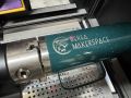 Makerspace logo engraved on the tumbler.

Troubleshooting
Common Problems and Solutions
Laser doesn't fire
- Check that the key is in the ON position
- Verify the E-stop is not activated (pull out and rotate counterclockwise)
- Check that the laser is properly connected to the computer
- Verify that Lightburn is set to the correct device ("Makerspace MOPA Laser")
Poor marking quality
- Ensure the material is properly focused (use the focus scale)
- Check that the lens is clean and free of debris
- Run a material test to verify optimal settings
- Confirm that the material is compatible with fiber laser wavelengths
Inconsistent results
- Check that the material is securely fixtured and not moving during marking
- Verify that the lens is clean
- Ensure the material is level and at the correct focus distance
No red dot / framing pointer
- Press the "Red Light" button on the controller to toggle it on
- Verify that the framing is enabled in Lightburn